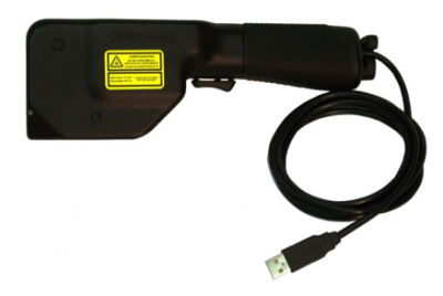
The HS730LE sensor is used to inspect the leading edge of blades or vanes used in aircraft and power system engines. Designed to scan both sides of the blade simultaneously, the sensor returns a complete profile around the radius of the blade, which allows the accurate measurement of the thickness and the plotting of the blade profile for comparison to its engineering design. The edge radius can also be analyzed.
The sensor connects to a laptop or tablet PC via a USB 2.0 cable. No other hardware or external power source is required.
Measurement Range – The unique design of the optics enables the sensor with a nominal 0.250” field-of-view (FOV) to scan a range of small to medium size blades. Thickness measurements are made at specified distances back from the leading edge of the blade, called the setback distances. The table below shows the range of blade sizes that can be measured using the HS730LE sensor. The range is expressed in terms of the maximum blade thickness at the maximum setback distance.
Resolution – With a 0.250” field-of-view (FOV), the HS730LE has a scanning resolution of 0.0004”, and measurement accuracy to within 0.0005” (12mm) on the blade thickness.
Connectivity – The handheld sensor is connected to a computer, laptop or tablet pc with a cable to a USB 2.0 port providing 500mA. No other hardware or external power source is required.
Feedback – Scanning is as simple as positioning the sensor on the edge of the blade and pulling the sensor trigger. Raw video and the plotted profile are displayed in real-time on the computer used with the sensor. Measurements are recorded when the trigger is released. Out-of-spec conditions are flagged with color symbols.
Programs – Separate programs can be developed for different blades, specifying different profile nominals and templates and different setback distances for thickness measurements.
Documentation – Data displayed in the table can be saved. The blade profile can be saved automatically for each scan, as well as an image of the plotted profile with measurement lines as shown in the plot window.